Medical Gas Pipeline Systems (MGPS): Components & Design
.webp)
Kate Williamson
Editorial Team, Asian Hospital & Healthcare Management
Medical gas pipeline design decides whether oxygen reaches a patient when seconds matter. This guide explains MGPS components, manifold systems, outlet standards, pipe sizing, and alarm requirements in plain, practical language, helping hospital planners, engineers, and facility managers build safe, code-compliant gas pipeline networks that perform reliably from day one.
Why Medical Gas Pipeline Design Is a Life-Safety Job, Not a Plumbing Job
What keeps a ventilator running at 3 a.m.? Behind every ICU bed, a network of pipes, valves, and alarms is quietly delivering oxygen, medical air, and suction. That network is the result of careful medical gas pipeline design, and it has to be reliable, uncontaminated, and impossible to mix up, because there is no second chance when a patient is breathing through it.
This guide walks through how an MGPS works, what goes into it, and how designers get from a floor plan to a working network. Whether you're a biomedical engineer, an architect, or a hospital administrator preparing a new wing, think of it as a practical MGPS hospital installation guide.
What Is a Medical Gas Pipeline System (MGPS)?
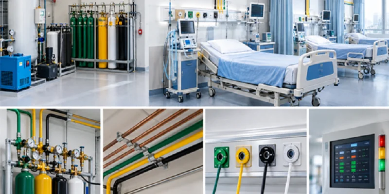
A medical gas pipeline system (MGPS) is a network of source equipment, pipework, valves, outlets, and alarms that delivers medical gases and vacuum from a central supply to the point of patient care.
Typical services include:
- Oxygen (O₂): respiratory support, anaesthesia, resuscitation
- Medical air: ventilators, neonatal care, driving anaesthetic equipment
- Nitrous oxide (N₂O): analgesia and anaesthesia
- Medical vacuum: suction in wards, theatres, and emergency rooms
- Surgical air (about 7 bar): powering surgical tools
- Carbon dioxide and anaesthetic gas scavenging: laparoscopy and waste gas removal
Different standards govern the details: ISO 7396-1, HTM 02-01 (UK), NFPA 99 (US), and local codes such as India's National Building Code and NABH requirements. Always confirm which one your project is bound by before you finalize drawings.
Core Hospital Gas Supply Pipeline Components
Think of an MGPS as a journey with five stops: source, distribution, isolation, delivery, and monitoring.
1. Source equipment
This is where gas is stored or produced. Options include liquid oxygen (LOX) tanks, cylinder manifolds, PSA oxygen plants, medical air compressors with dryers and filters, and vacuum pumps with receivers. Smart designs always include a backup, because a single source is a single point of failure.
2. Pipework
Medical-grade copper is the usual choice, degreased and supplied in sealed lengths (EN 13348 or ASTM B819). Joints are brazed under a continuous nitrogen purge to stop internal oxidation, which would otherwise flake into the patient's breathing circuit. Stainless steel and approved alternatives are used in some regions.
3. Valves and isolation
Zone valve boxes (ZVBs) let staff isolate a single ward or theatre during maintenance or fire without cutting off the whole hospital. Main shut-off valves, riser valves, and branch valves complete the picture.
4. Terminal units (outlets)
These are the wall, pendant, or bed-head connections where clinicians plug in. They are covered in detail below.
5. Monitoring and alarms
Pressure switches, gauges, and alarm panels keep watch so people don't have to. More on that shortly.
How Does a Central Medical Gas Manifold System Work?
A central medical gas manifold system automatically supplies gas from a duty bank of cylinders and switches to a standby bank when the duty bank runs low, with no interruption in flow.
A well-designed manifold typically has:
- Duty (running) bank and standby (reserve) bank of cylinders
- Automatic changeover controlled by pressure signals
- Two-stage pressure regulation with duplicate line regulators, so one can be serviced without a shutdown
- A third emergency reserve, often a smaller bank, as a last line of defence
- Non-return valves and flexible tails to keep cylinders isolated from each other
Design tip: Place manifold rooms at ground level, with good ventilation, fire separation, secure access, and easy truck access for cylinder deliveries. A manifold room tucked in a basement corner becomes a maintenance headache for decades.
For larger hospitals, liquid oxygen with a cylinder manifold backup is the norm. For smaller facilities, a PSA plant plus manifold is increasingly common, especially where deliveries are unreliable.
Medical Gas Outlet Standards: What You Need to Know
Outlets are the one part of the MGPS that every clinician touches daily, so standards here are strict.
Key points on medical gas outlet standards:
- Gas-specific connectors. Each gas has a unique, non-interchangeable fitting (DISS, Schrader, BS 5682, DIN, AFNOR, and others), so an oxygen hose can never be plugged into a vacuum outlet.
- Colour coding. Under ISO conventions, oxygen is white, medical air is black-and-white, and vacuum is yellow. The US (NFPA) uses a different scheme: green for oxygen, yellow for air, and white for vacuum. Check which applies in your country.
- Terminal unit standard. ISO 9170-1 covers terminal units for compressed gases and vacuum.
- Self-sealing. Outlets must shut off automatically when a probe is removed.
- Testing. Each outlet should be tested for leakage, flow, and gas identity before commissioning.
Typical outlet counts (always confirm against your local guideline and clinical brief):

Medical Gas Pipeline Design: The Step-by-Step Workflow
If you're wondering where to begin, here's the sequence most experienced designers follow.
- Clinical brief. Count beds, theatres, and specialities. Ask clinicians what equipment they'll use.
- Gas demand estimate. Convert outlets and equipment into expected flow.
- Source selection. Choose between LOX, manifold, PSA, or a hybrid, and plan redundancy.
- Route planning. Run risers and branches in accessible ducts and ceiling voids, away from electrical hazards and heat sources.
- Pipe sizing. Calculate diameters for each section (explained next).
- Valve and alarm placement. Position ZVBs outside the area they serve, with area alarms nearby.
- Drawings and specification. Produce coordinated drawings that show gas types, labels, and pressures.
- Installation, testing, and commissioning. Verify purity, pressure, leaks, cross-connection, and alarm function, then document everything.
Hospital Gas Line Sizing Calculation: A Simple Walkthrough
Gas line sizing is the process of choosing pipe diameters so that gas arrives at every outlet at the right pressure and flow, even at peak demand.
Undersized pipes starve the far end of the building. Oversized pipes cost more and waste space. The goal is to keep pressure drop and velocity within limits.
The basic method
- List the outlets on each branch.
- Assign design flow per outlet. Typical oxygen figures range from about 6 to 10 L/min forward outlets, with higher values for theatres and ICUs, depending on the standard.
- Apply a diversity factor. Not every outlet runs at once. Larger groups of outlets use lower diversity percentages.
- Add specific equipment loads, such as ventilators or high-flow therapy units.
- Calculate total flow for each pipe section.
- Select the pipe diameter using flow charts or software, keeping pressure drop within your standard's limit (often a few percent of nominal pressure) and velocity within safe limits.
Illustrative example (not for real design use)
Suppose an ICU has 10 beds, each with 2 oxygen outlets at 10 L/min, and a diversity factor of 50%.
Total connected flow = 10 beds × 2 outlets × 10 L/min = 200 L/min
Design flow = 200 × 0.5 = 100 L/min
You'd then look up the smallest copper pipe size that carries 100 L/min over your branch length without exceeding the allowed pressure drop. A short run might manage with 15 mm or 22 mm pipe, while a long run needs the next size up.
Why a pressure drop matters: nominal pipeline pressure for most gases is around 4 bar (7 bar for surgical air), and vacuum is typically around -40 kPa or lower at the terminal. If the drop is too large, ventilators and flowmeters under-deliver.
Always run final sizing through a qualified MGPS engineer or approved software. This example is a teaching aid, not a design document.
Medical Gas Alarm System Requirements
Alarms are the system's nervous system. If the supply fails, people must know immediately, in the right place, and in a way they can't miss.
Core medical gas alarm system requirements usually include:
- Master alarms in a continuously staffed location (such as the engineer's office or nurses' station), showing the status of source equipment
- Area alarms in each department, monitoring pressure downstream of the zone valves
- Local alarms on plant such as manifolds and compressors
- Audible and visual signals with distinct priority levels: normal, warning, and emergency
- Pressure thresholds, commonly about ±20% from nominal for high and low pressure warnings (check your standard)
- Independent power or battery backup, so alarms still work in a blackout
- Mute with re-sound, so a muted alarm doesn't stay silent forever
- Regular testing and documented records
Position area alarms where staff can both see and hear them without leaving the clinical zone. An alarm in a closed store room is only decoration.
Common Medical Gas Pipeline Design Mistakes (and How to Avoid Them)
Experienced engineers see the same issues again and again:
- Underestimating future demand. Hospitals grow. Leave spare capacity in risers and plant.
- Poor cleaning and brazing practice. Contamination causes patient harm and costly re-testing.
- ZVBs placed inside the room they control. That defeats their purpose in an emergency.
- No single point of accountability. Clear ownership between designer, installer, and tester avoids finger-pointing at handover.
- Skipping third-party verification. An independent authorised tester catches what the installer misses.
- Weak documentation. Without as-built drawings, every future modification becomes guesswork.
Frequently Asked Questions
What is the primary purpose of medical gas pipeline design?
To deliver the right gas, at the right pressure and flow, to every patient point, continuously and without contamination.
Which standard applies to MGPS design?
It depends on location. ISO 7396-1 is the international reference, HTM 02-01 is used in the UK, NFPA 99 in the US, and national or state codes apply elsewhere.
What pressure do medical gas pipelines run at?
Most gases run at around 4 bar, surgical air at about 7 bar, and vacuum at roughly -40 kPa or lower at the terminal.
Why is copper used for medical gas pipes?
It's durable, corrosion-resistant, naturally antimicrobial, and can be supplied in a clean, degreased state suited to medical use.
How often should MGPS alarms be tested?
Typically, as part of a planned maintenance schedule, with periodic functional checks. Frequency depends on local regulations and hospital policy.
Can one pipeline carry different gases?
No. Each gas needs its own dedicated, clearly labelled pipeline to prevent dangerous cross-connection.
Final Thoughts
Good medical gas pipeline design is a team effort between clinicians who know what patients need, engineers who know how to deliver it, and installers who take pride in clean joints and careful testing. Get the components, sizing, outlets, and alarms right, and nobody notices the system at all, which is exactly the point.
If you're planning a new hospital wing or upgrading an old one, start with the clinical brief, choose a resilient supply, size every line carefully, and verify everything before the first patient is connected.








-(1).webp)